











Fiber Laser Cutting Machines transform CAD drawings into finished metal parts by synchronizing CNC movement with a highly focused laser and the appropriate assist gas. Controller software reads the cutting path, servo motors are commanded to move the cutting head as required, the laser source is turned on/off as required and optical components are used to focus the laser beam on the cutting sheet. Assist gas then removes molten metal from the kerf.
Cut quality does not depend on laser power only. It also depends on source, cutting head, optics, nozzle, controller, motion system, machine structure, chiller and gas supply.
The article deals with flatbed fiber laser cutting machines for cutting carbon steel, stainless steel, aluminum and other approved materials.
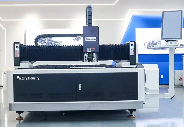
How Does a Fiber Laser Cutting Machine Turn a Drawing into a Part?
The machine is doing several things at once, so the cutting file, motion, laser, focus and gas supply are all running from the same program.
From CAD File to CNC Commands
From DXF/DWG files, the parts are organized on the sheet by a nesting program, and the parts are sorted in the cutting order to minimize scrap.
The CNC controller converts the file into movement, piercing, speed, focus, and gas commands. Problems such as duplicate lines, open contours, or poor lead-ins can affect the result before cutting even starts.
From Laser Beam to Finished Kerf
The fiber laser source delivers the laser beam via a delivery fiber to the cutting head. The optics within the cutting head then focus the laser beam down to a spot where it has sufficient power density to melt or vaporize the metal.
The narrow slot left by the beam is called the kerf. Its width and edge quality depend on power, speed, focus position, sheet thickness, and material condition.
Why Assist Gas Matters
Assist gas pushes molten metal out of the kerf and changes the final edge.
Oxygen is often used for carbon steel. Nitrogen is commonly chosen for cleaner stainless steel and aluminum edges. Compressed air can reduce operating costs on suitable thin sheets.
Gas purity, pressure, nozzle size, and nozzle centering all affect dross and edge color.
What Are the 10 Core Systems of a Fiber Laser Cutting Machine?
Each system controls a different part of the cutting process. When one system becomes unstable, the defect may appear somewhere else.
1. Fiber Laser Source
The fiber laser source generates the beam and provides the available cutting power.
The correct power depends on material, thickness, expected speed, and working hours. Stable output is more important than choosing the highest wattage available.
2. Delivery Fiber and Cutting Head
The delivery fiber carries the beam from the source to the cutting head.
The cutting head focuses a beam of light onto the sheet. The fiber and head must be protected from impact, contamination, sharp bends and moisture.
3. Collimating, Focusing, and Protective Optics
The internal optics shape the beam and place the focal point at the required position.
A protective window shields the more expensive optics from dust and spatter. When it becomes dirty or damaged, beam transmission drops and heat can build up inside the head.
4. Nozzle and Capacitive Height Control
The nozzle directs assist gas into the kerf. Its size, condition, centering, and distance from the sheet affect cutting stability.
Capacitive height control keeps the nozzle at the programmed distance from the material. Poor calibration, a damaged ceramic ring, or an uneven sheet may cause unstable height or collisions.
5. CNC Controller and Nesting Software
The CNC controller coordinates movement, laser output, focus, piercing, and gas selection.
Nesting software controls part layout and cutting order. A poor sequence may increase scrap, trap parts, or create too much heat in one area.
6. Servo Motors and Drives
Servo motors move the cutting head according to CNC commands.
Their response affects acceleration, corners, small holes, and repeated dimensions. A machine may still cut straight lines while motion accuracy is already starting to drift.
7. Gearbox, Rack-and-Pinion, and Linear Guides
Gearboxes, racks, and guides convert motor rotation into smooth axis movement.
Wear, backlash, contamination, or poor lubrication may cause rough circles, shifting dimensions, vibration, and uneven corners.
8. Machine Bed, Gantry, and Worktable
The machine bed supports the full cutting system. The gantry carries the cutting head, while the worktable holds the sheet.
A rigid and properly leveled structure helps maintain accuracy. Damaged slats or heavy slag buildup may lift thin sheets and change the nozzle distance.
9. Water Chiller and Cooling Circuit
The chiller controls the temperature of the laser source and, where required, the cutting head.
Poor cooling may cause alarms, unstable output, condensation, or shorter component life. The chiller capacity must match the laser power and daily working schedule.
10. Assist Gas and Fume Extraction Systems
The gas system includes the gas source, filters, regulators, pipes, and valves. It must provide stable flow at the cutting head.
The extraction system removes fumes and fine particles from the cutting area. Proper extraction protects operators and reduces contamination inside the machine.
How Do These Systems Control Cut Quality?
Cutting defects often come from several conditions acting together. Randomly increasing power or reducing speed may hide the problem, but it does not always solve it.
Power, Focus, and Gas Must Match
Too little power may leave uncut sections. Too much heat can widen the kerf or increase dross.
Wrong focus may cause slow piercing, rough lower edges, or incomplete separation. Automatic focus helps with material changes, but the programmed value still needs to match the actual material and thickness.
A damaged or off-center nozzle may also produce an uneven edge even when the power and speed settings look correct.
Motion Accuracy Appears in Corners and Holes
Small circles, sharp corners, and repeated parts often show motion problems before straight cuts do.
When dimensions shift or corners become rough, check the guides, rack engagement, servo alarms, machine level, nozzle centering, and material flatness before increasing laser power.
Cooling and Extraction Affect Long Shifts
A machine may cut well at the start of a shift and lose consistency several hours later.
When this happens, check water temperature, coolant flow, gas pressure, extraction airflow, cabinet temperature, and protective-window condition. The problem may sit outside the cutting parameter table.
Which System Should You Check When a Cut Goes Wrong?
Start with the visible symptom instead of checking every component in the same order.
Heavy Dross or Incomplete Cutting
Check focus position, nozzle condition, gas pressure, cutting speed, and sheet flatness.
If several different materials fail in the same way, inspect the protective window, beam delivery, cooling condition, and laser source output.
Poor Circles or Shifted Dimensions
Check linear guides, racks, gearbox play, servo status, machine level, and the cutting sequence.
Heat buildup may also move thin parts, especially when too many small features are cut in the same area.
Unstable Output or Frequent Alarms
Check chiller temperature, coolant flow, filters, extraction airflow, gas delivery, and cutting-head temperature.
Repeated protective-window contamination may point to poor sealing, weak extraction, nozzle damage, or an unsuitable piercing process.
Which Machine Fits These Requirements?
A suitable machine should handle normal production reliably. Maximum cutting thickness should not be the only selection point.
Where the VIF-A Fits
The VIF-A Laser Cutting Machine combines a fiber laser source, cutting head, servo motion, linear guides, reducer, control system, and tube-welded bed.
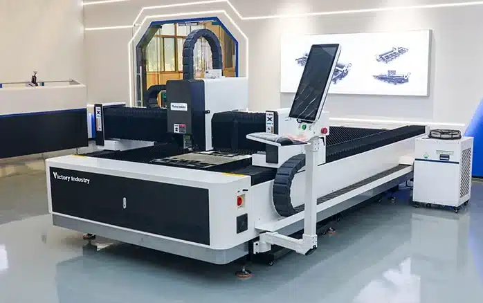
Available configurations cover different working areas and laser power levels. The final choice depends on material type, normal thickness, sheet size, edge requirement, and daily output.
Its tube-welded bed and aviation aluminum beam provide a stable machine base while keeping the moving gantry relatively light. This setup suits electrical cabinets, brackets, machine covers, metal furniture, and general sheet-metal parts.
What to Send Before Requesting a Configuration
Prepare the following information before asking for a quotation:
- Material types
- Common and maximum thickness
- Sheet dimensions
- Part drawings
- Daily production target
- Edge quality requirement
- Factory voltage
- Available assist gas
- Loading or unloading needs
Victory Industry supplies laser equipment, CNC forming machines, and automation systems. Its service support includes configuration, installation, operator training, parameter guidance, maintenance planning, and spare-parts advice.
For a suitable configuration, contact Victory Industry with your material list, drawings, and expected output.
Conclusion
A fiber laser cutting machine works by coordinating the beam, optics, gas, CNC control, motion system, machine structure, cooling, and extraction.
When a cut goes wrong, start with the symptom. Heavy dross usually leads to focus, gas, nozzle, or speed checks. Poor circles may point to guides, racks, servo motion, or machine level. Unstable cutting during long shifts may come from cooling, gas delivery, extraction, or optical contamination.
The right machine should be selected around normal production, not only maximum power or maximum thickness. Material range, daily output, maintenance access, gas supply, operator training, and after-sales support all matter.
FAQ
Q1: What Are the Main Systems in a Fiber Laser Cutting Machine?
A1: The main systems include the laser source, delivery fiber, cutting head, optics, nozzle and height control, CNC system, servo motion, mechanical transmission, machine structure, chiller, assist gas, and extraction system.
Q2: Which System Has the Greatest Effect on Cut Quality?
A2: No single system controls the full result. Focus, nozzle condition, gas flow, motion accuracy, cooling, and material quality work together.
Q3: Does Higher Laser Power Always Produce a Better Cut?
A3: No. Higher power may increase speed or thickness capacity, but poor focus, weak gas flow, nozzle damage, or incorrect speed can still produce rough edges and heavy dross.
Q4: Why Does a Fiber Laser Cutting Machine Need Assist Gas?
A4: Assist gas removes molten metal from the kerf and helps control oxidation, dross, edge color, and final surface condition.
Q5: Which Parts Need Regular Maintenance?
A5: Regular checks should cover nozzles, protective windows, ceramic rings, guides, racks, filters, gas lines, the water chiller, extraction equipment, and safety systems.