











For industrial fiber laser cutting of metal sheet, the useful number is the tolerance measured on the finished part. SendCutSend, for example, lists +/-0.005 in (+/-0.127 mm) for laser-cut parts under 12 in and +/-0.010 in (+/-0.254 mm) for larger parts. Those are that provider’s limits, not a universal machine rating or a Victory Industry specification.
The positioning figure still matters, but it describes axis movement under a defined test. A finished bracket also reflects material, thickness, focus, kerf compensation, corners, heat, and the inspection method.
For a machine purchase, mark the critical dimensions on your drawing and test them with your material. This keeps the comparison tied to production instead of one clean sample or one brochure number.
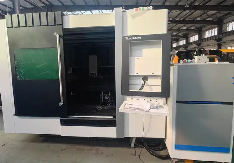
What Accuracy Means in Laser Cutting
Positioning Accuracy and Repeatability
Positioning accuracy describes how closely an axis reaches a commanded position. Repeatability describes the variation when it returns under the same conditions. ISO 230-2 covers tests for numerically controlled machine-tool axes. Neither figure states the tolerance of every finished part.
Cut parts near startup and later in a realistic run. Changes in temperature, optics, sheet condition, or gas delivery may appear on the part even when the axis specification remains the same.
Part Tolerance Is Not the Same as Machine Specification
Finished-part tolerance also depends on plate flatness, edge taper, focus, gas, acceleration, and thermal movement. A machine specification measured under controlled conditions should not be copied onto a drawing as a promised part tolerance.
Ask what was measured, where the datums sit, which instrument was used, and whether the part was cooled and deburred. Use the same drawing and inspection rules when comparing suppliers.
How Kerf Width Affects Part Dimensions
Why the Beam Removes Material
Kerf width is the material removed by the cut. CAM software or the controller offsets the path by a configured value; it does not automatically know every change in actual kerf. Power, speed, focus, nozzle, gas, material, and thickness all matter.
As a simple geometry example, if the kerf is 0.20 mm and the path follows the beam center, the offset at one finished edge is about 0.10 mm. Move an outside contour toward the surrounding scrap and a hole contour toward the scrap inside it. Check the controller’s convention and avoid compensation in both CAD and CAM. This is an illustration, not a measured Victory Industry value.
Measure Kerf on the Material You Use
Use a coupon with a straight edge, corner, slot, hole, and repeated pattern. Measure after cooling and inspect both faces if taper matters. Keep separate settings for common materials, thicknesses, and gas setups.
Carbon steel brings its own choices of speed, focus, nozzle, and gas. How to Optimize Fiber Laser Cutting Parameters for Carbon Steel is useful when another thickness produces dross, a wider kerf, or a burned edge.
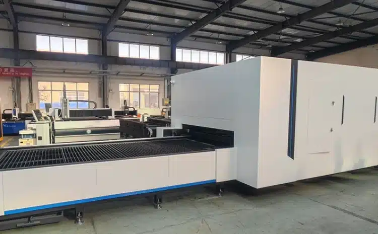
Small Holes, Corners, and Complex Profiles
Hole Diameter and Thickness Ratio
A small hole can look round from above while its lower edge is tapered or rough. Control becomes harder as the hole gets small relative to sheet thickness, and no single ratio suits every job.
Put the smallest production hole in the sample program. Measure it in more than one direction, inspect the lower edge, and check the fit required by the next operation.
Corners and Acceleration
At a corner, the head slows and changes direction. If power stays too high for the lower speed, excess energy can widen or burn the corner. Motion tuning also affects how closely the axes follow the path.
Try short segments and tight corners from a real panel. Compare them with a long straight cut on the same sheet to separate recipe problems from motion problems.
Heat and Sheet Movement
Heat input, temperature gradients, and released sheet stress can move a thin part. A small piece may also tip on the slats. Cut order, support tabs, clamps, and plate flatness affect the result.
What Makes Accuracy Stable Across a Batch?
Beam, Focus, and Nozzle Alignment
A worn nozzle, dirty protective window, collision, or incorrect focus can change the cut without an obvious alarm. Check beam centering and optics before tuning a new parameter set.
Automatic focus helps with changeovers, but it still needs calibration. One alloy or surface condition may require a different position from another.
Motion System and Machine Bed
Guides, racks, servos, and the bed all affect motion. Wear, loose parts, or contamination may show up on a long profile. Compare cuts at several places on the working area.
Cooling and Operating Environment
Track chiller temperature, gas pressure, power, and shop conditions during a longer run. Keep early and late samples with their settings if the dimensions shift.
How to Test a Laser Cutting Machine Before Purchase
Bring Real Drawings and Materials
Prepare actual grades, thicknesses, holes, slots, corners, and surface requirements. Add a part that goes on to bending, welding, tapping, or assembly, with critical dimensions and datums marked.
Record the model, power, gas, nozzle, focus, speed, plate position, and cycle time. Measure several cooled parts from different sheet areas with a suitable calibrated instrument. State whether burrs were removed, then list each result, the largest deviation, and the spread. A short trial screens a machine; it does not certify long-term process capability.
Repeat the Test After the Machine Warms Up
Cut the same feature near startup and later under the same inspection rules. Compare dimensions, hole shape, edge quality, and movement under conditions that resemble normal production.
If a demonstration only uses a perfect sample on thin sheet, ask how it represents your work. Include the difficult features and the expected limits.
How Software and Automation Affect Precision
Nesting, part spacing, lead-ins, and cut sequence affect heat and movement. Height sensing, collision protection, and automatic focus can reduce setup variation when properly calibrated and maintained.
Loading systems may reduce handling variation, but an exchange table does not improve inherent axis accuracy by itself. 4 Types of Industrial Laser Cutting Machines can help you compare formats before choosing the working area and automation package.
Choosing a Precision Laser Cutting Machine
Industrie de la victoire’ s Fiber Laser Cutting Machine range covers different metal-cutting configurations. For flat-sheet work, compare the Sheet Laser Cutting Machine options with your working area, thickness mix, smallest feature, output, and loading plan. Request sample results from the exact proposed model.
Compare the source, head, motion system, calibration, cooling, gas control, software, and maintenance access. Victory Industry’s services cover installation, training, technical support, and maintenance. Review the company’s À propos de nous information and send drawings through the Contact Page to agree on cutting and inspection conditions.
Conclusion
For metal sheet, laser cutting accuracy is the result measured on the finished part under stated conditions. Positioning, repeatability, kerf, edge taper, heat, and sheet movement explain the result, but they do not replace an inspected sample.
Start with dimensions that can stop assembly. Check them across the sheet and across a realistic run, then keep the settings and measurements together. That gives you a sound basis for choosing a machine.
FAQs
What Accuracy Can a Laser Cutting Machine Achieve?
It depends on the part and process. The published example above is +/-0.005 in for laser-cut parts under 12 in and +/-0.010 in for larger parts, not a universal rating. Put your required tolerance on the drawing and request measured samples.
Is Kerf Width the Same as Cutting Accuracy?
No. Kerf is the material removed by the cut. The offset accounts for that width, while the finished dimension still depends on motion, focus, heat, material, and sheet movement.
How Can I Improve Small-Hole Quality?
Inspect the nozzle, centering, protective window, focus, gas, and the underside of a test hole. Change one setting at a time, then measure the hole in more than one direction.
Does a Thicker Sheet Reduce Laser Cutting Accuracy?
Thickness can make piercing, taper, heat input, and lower-edge quality harder to control. Test the actual grade and thickness instead of applying a tolerance taken from a thinner sample.
What Should Be Included in a Machine Accuracy Test?
Use real materials, the smallest holes and slots, tight corners, long profiles, and repeated features. Record the cutting conditions, inspect cooled parts from different sheet positions, and compare results near startup and later. Agree on datums, measurement methods, and acceptance limits before cutting.